
Dipoles and Vs!

Dipoles at the correct height are not only stealthy antennas, they work great!
Here is a six minute video that details the dipole and loop antennas that netted us DXCC and WAS in 9 days with 100 watts! The antennas are a bit difficult to see in the video, but that underscores how stealthy they really are!
In some circles, a dipole antenna doesn’t get a lot of respect. Sure, dipoles are great starter antennas - easy to build, very stealthy and inexpensive, but there’s a perception some folks hold that dipoles for bands 20 meters and up just don’t quite cut it for contesting and DX. I used to be one of them!
It’s understandable. Dipoles are often rated at about 2 dBi of gain over an isotropic radiator, which sounds pretty unimpressive. By the way, if you are unfamiliar with isotropic radiators, they are theoretical antennas that radiate an equal amount of signal in all directions, like a sphere, so they have no gain in any direction by default. The 2 dBi you see associated with dipoles is the resulting gain of the donut shaped radiation pattern surrounding the length of the antenna.
But wait, that 2 dBi of gain is a measure of the antenna’s performance in free space. Unless you are planning a shuttle mission soon, it is irrelevant! Watch what happens to the gain of an ordinary dipole when placed 60% of one wavelength above a typical earth ground (in this case, a 20 meter dipole at 42 feet):
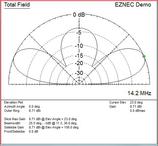
20 Meter Dipole at 42 feet. 8.71 dBi of gain and take off angle at 23 degrees.
All of a sudden you’ve got nearly 9 dBi of gain! What’s more, the prominent lobes are respectably close to the horizon, which is much better for working more distant stations.
Next time you are looking at antenna specs and see comparisons to a dipole, find out if the manufacturer is comparing their antenna to a dipole in free space or over real ground. All antennas radiate the same amount of energy. The only difference in antennas is the direction where your signal is concentrated.
If you're still skeptical about the very good performance of a dipole, take a look at this article, written by Hex Beam manufacturer, Leo Shoemaker, K4KIO! Then read the next section about how much height matters below!
Height Matters, a Lot!
Here’s the single most important factor in determining how well our dipoles perform. It's all about height! Look what happens if we drop our dipole to 20 feet above ground.
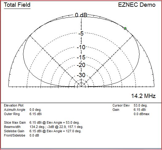
20 Meter Dipole at 20 feet. 6.15 dBi (2.56 dBi down from optimum) and near vertical radiation pattern, we have an NVIS cloud burner.
If we drop the 20 meter antenna to 20 feet above ground, we not only lose over 2.5 dBi of gain, we’ve got a classic cloud burner, sending almost all our RF energy straight up! That’s fine if the only stations we want to talk to are nearby. What’s not lost to outer space will be reflected by the ionosphere straight back down, out to a couple hundred miles depending on conditions. On the other hand, if we want our signal to cover a lot of area to get a good QSO rate going, work all the sections in November Sweepstakes or get our DXCC totals up, this is not the configuration we want!
In addition to the free space, 2 dBi number comparison, I suspect that the other reason many folks view dipoles without enthusiasm is that they tried one first starting out, probably too low as in this example, got frustrated and moved on.
Keep in mind, most beams are nothing more than dipoles with directors and reflectors. When folks erect beams, they typically put them at reasonable heights, so they experience the same benefits of height above ground that we enjoy with properly erected dipoles. Beams at the proper height work excellent in one direction. Dipoles at the proper height work very well in two directions.
More Altitude, No Gain?
Look what happens when we raise our 20 meter dipole to 52 feet, 10 feet higher than the altitude that gave us 8.71 dBi of gain.
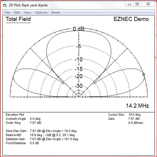
20 Meter Dipole at 52 feet. 7.67 dBi of gain and take off angle at 19 degrees.
We lose about a 1 dB of gain that we could have had at 42 feet. Raising the antenna higher than the optimum gain target doesn't generate the drop off that a low antenna does, so it is better to be too high than too low, but there isn't a compelling incentive to go another 10 feet over the 42 foot target for a 20M dipole.
There is a sweet spot height at about 60% of the wavelength of the target frequency that maximizes the performance of a dipole. For good gain in two directions to the broadside of the wire, place each dipole at a height of 60% of the target frequency wavelength.
Random Branches - Vs to the Rescue!
But what if you don’t happen to have two branches exactly 42 feet high and far enough apart to string your dipole at optimum height? Don’t worry, most of us don’t. Here’s a way you can string many dipoles in a V orientation, only needing one branch at ANY height, just so long as it is higher than you need for the lowest frequency dipole you plan to fly.
First, just a bit more theory. If we only have one support for our dipole(s), it will have to hang from a rope holding the dipole's center. Then we can tie off the ends by running a guy line at each end of the wire dipole to a ground stake, nearby tree, etc. That means the ends will be angled in an inverted V configuration, so what does that do to our radiation pattern?
Here is a plot of our 20M dipole, now in a V configuration with the two ends each sloping at 30 degrees:
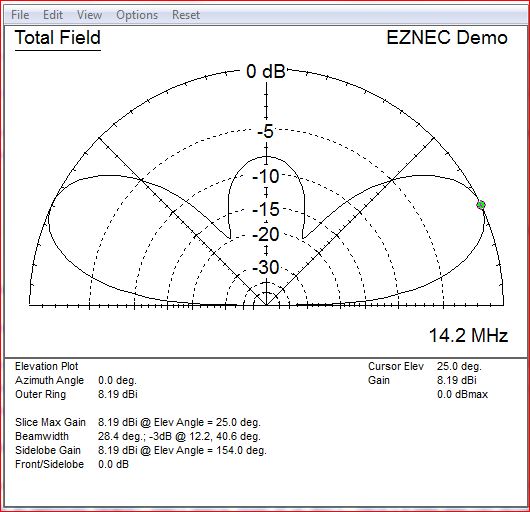
20 Meter Dipole V at 42 feet with wires sloping down at 30 degrees. 8.19 dBi of gain and take off angle at 25 degrees.
As you can see, our gain is still over 8 dBi, we lose less than 1 dBi by slanting the wires and the radiation pattern is still quite similar to the optimum configuration. The point is, while we lose a small amount of gain by choosing the V configuration, we have the ability to set exactly how high we want the antenna, which likely offsets whatever we might lose by trying to use two random branches at varying heights. We can slope the wires down as much as 45 degrees and still have near optimum gain and a low angle pattern.
One Branch, One Line, Multiple Stacked Dipole V Antennas, All Kicking Butt!
Since each dipole works best at its optimum height and that height is considerably different for each frequency band, it is easy to attach multiple dipoles to a single line and raise each to its own optimum height for maximum performance. This is a concept drawing for the system I have set up here for 20, 15 and 10 meters.
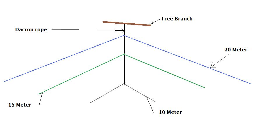
Three individual dipoles on a single line. The set is easily raised to their individual optimum performance heights.
Here is an actual picture. The one disadvantage of a really stealthy antenna system is that it is hard to show you what it really looks like!
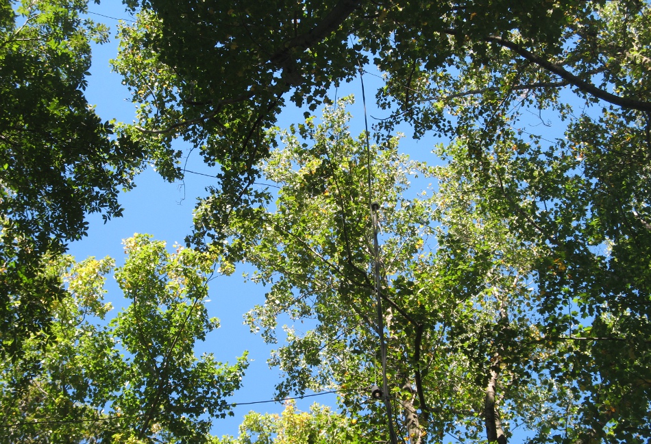
20M, 15M and 10M stacked inverted Vs. There is more of a downward angle to the dipoles than it appears from this photo angle.
This chart summarizes the dimensions and target height for dipoole antennas. For the lower bands, reaching the target height isn't realistic for most of us. In those cases, just go as high as you can.
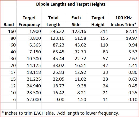
Dipole lengths and optimum target heights of .6 wavelength above ground.
Building the dipole is super easy. Just cut the wire for the desired band to the lengths above, but leave a little extra as you will likely have to tune it for a good match in your specific environment. The hardest part might be getting the line over a good branch, but an EZ Hang or baseball with a screw eye inserted and fishing line attached will do the trick.
For each dipole, you just need wire, two insulators (one for each end) and a center insulator / connector such as a CQ dipole center, SO239, center hang connector (Part # 801 at thewireman.com). You'll also need some dacron rope (Dacron rope, part # 816 at thewireman.com). Please see the complete parts list at the bottom of this page.
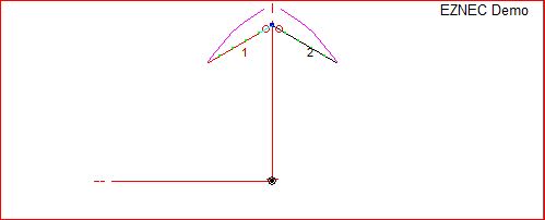
Dipole Orientation Matters Too!
Dipoles have gain broadside to the direction of the way you orient your wire and are down more than 10 dB off the ends, so aiming them in the right direction is really important! I use two sets here, hung perpendicularly, to maximize the benefits dipoles offer.
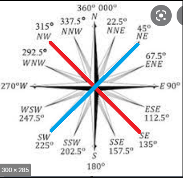
Red dipole set radiates broadside NE / SW
Blue dipole set radiates broadside NW / SE
From here in Maryland, it really matters for us, as SE is great for the Caribbean, but the Caribbean and parts of South America are right off the end (null) of the NE dipole for Europe (and vice versa). A flick of the antenna switch and I am instantly on the direction I want. For me:
NE = Europe and Northeast US
NW = Hawaii, Alaska, Japan, Australia and Northwest US
SE = SA, Caribbean
SW = SW US & Mexico
For lots more details on how I have my two dipole sets oriented and change direction with the flick of an antenna switch, please see these details here!
Conclusion
By stacking dipoles or Vs at optimum heights, we can achieve over 8 dBi of gain in two directions, which is not only a good bit of gain for working DX and holding our own in pile ups, it offers advantages over a one directional beam for running a frequency, participating in round table nets, etc. This is all accomplished with a very inexpensive, stealthy, neighborhood friendly antenna system that is very easy to build. The dipoles will have a null off the ends, so orient them for you favored directions. If you want to control the direction of your signal, you can learn how I do that here!
Parts List
The following is a list of the parts that you will need to build six dipoles (a set of two dipoles for each band (20, 15 and 10 meters) at 90 degree orientation).
- Wire. This plan will require about 150 feet. Here is a 500 foot spool from Home Depot.
- 6, CQ dipole center, SO239, center hang, heavy duty, UV resistant. Item 801 here: https://thewireman.com/product/cq-dipole-center-so-239/.
- 1, Ameritron RCS-10, 8 position remote coax switch box. By the way, a remote coax switch box is an excellent investment. You'll actually save money by not having so many long runs of coax back to your house, you won't have so much coax cluttering up the shack and you can easily change bands with the flick of a switch! http://www.hamradio.com/detail.cfm?pid=X7-000001.
- Sufficient quantity of 4 conductor cable (could even be telephone wire) to control your switch box: http://www.amazon.com/RadioShack-100-Ft-4-Conductor-Phone-Cable/dp/B007Z8DRFU/ref=sr_1_9?ie=UTF8&qid=1429109730&sr=8-9&keywords=telephone+wire.
- Sufficient coax (from rig to switch box plus six runs from switch box to dipoles).
- 14 PL 259 connectors (order coax with connectors attached if you would rather not solder the connectors): https://thewireman.com/product-category/connectors/.
- 12 Insulators (item 810): https://thewireman.com/product/budwig-end-insulators/.
- Sufficient quantity of Dacron rope (item 814 or 816): https://thewireman.com/?s=dacron&post_type=product
Two important safety tips and a disclaimer: First, contact with overhead power lines can kill you! Always be mindful of the location of your power lines, your ladders, handling antennas, other metallic objects, etc. Second, you should always evaluate the placement of your antennas and address any RF exposure risks as detailed here. Any actions that you take based upon the information presented here shall be solely at your own risk. Neither N3FJP Software, our employees or any of our contributors shall be held liable for any actions taken based upon the information presented on this website.
![]()
Copyright 1997-2014, N3FJP Software - Affirmatech, Inc